I’m Going In.

•July 29, 2012 • Leave a Comment

IMG_1787

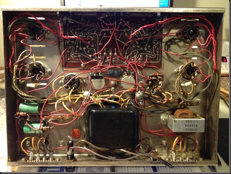
Back at the end of the Cold War,  when high technology usually referred to electronic hardware, I was all over, in, and out of this amp. Furthermore, with the analog measurement equipment available to me back then, we checked the specs of this Dynaco and every other piece of audio gear we could find.

But until recently, I hadn’t cracked the screws to this old amp in 25+ years. Once I was inside I could see the effect of the last 2 1/2 decades.

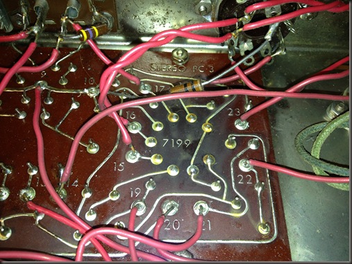
For example, below you’ll see the effects of slow-cooking a circuit board for 50 years.

IMG_1790

The area under the 7199 tube is noticeably discolored from all the heat thrown off by the tube. This picture also shows that the amp was wired with solid wire. Looks like 18 gage. With today’s thinking, this would be an application that calls for stranded wire. Perhaps the Dynaco folks thought that solid wire was easier for the kit-builders.

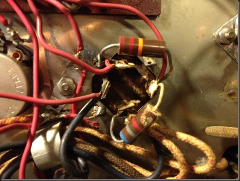
There’s signs that the multi-cap needs replacement. Notice below the evidence that the cap has leaked. There’s evidence of corrosion from the capacitor tabs downward,. In the picture it is easy to see on the  to the 6800 ohm resistor. I have yet to check this with a capacitance meter.

IMG_1788

Dynaco Stereo 70

•July 23, 2012 • Leave a Comment

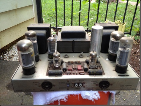
After 30 years, I’m finally getting around to fixing this. More to come soon.

IMG_1785

I bought this, along with a Dynaco PAS3 preamp, at a flea market abound 1980. I never did anything to the power amp, but it needs an upgrade to the input RCA jacks and the output speaker connectors. Maybe more.

Arduino Mega Shield Template in Eagle – Improved!

•January 2, 2012 • 2 Comments

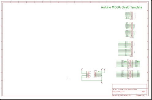
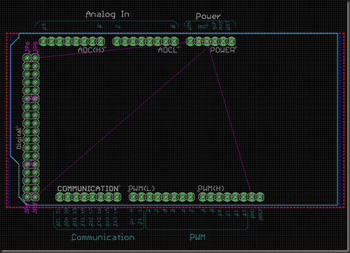
Exactly one year ago I made a blank shield template for my Arduino designs. I’ve had the opportunity to use it several times. It was OK, a serviceable starting point for Arduino-based projects. I’ve just recently made improvements that will help speed up the design process:

  • Signal names match names in the Arduino silk screen

  • Top layer has a copper pour for the +5v circuit

  • Added a frame to the schematic

  • Arranged all Arduino connections on the right-hand side of the schematic page.

image

These are small changes, but they make a big difference in your ability to organize and check your design effort.

image

For instance, I like my circuits to “read” from left to right. For me this is less confusing than other formatting choices. As for signal names, other shields cobbled from the Arduino reference design often preserve the Atmel signal names, rather than the signal names from the Arduino Hardware Description web pages. I hope these files work for you.

Get the files here:

http://www.mediafire.com/?1z98ws4wyh232d6

Why nothing gets done around here

•December 29, 2011 • Leave a Comment

“My computer won’t read my CDs”, said my darling wife. Her computer is a relic, but I was hoping that it would last until 2012. She wanted to put songs from Xmas CDs onto her iPod.

I’ve only ripped a CD on rare occasion, and I dislike iTunes, so I was not familiar with this. I reviewed the steps involved. Her process seemed hunky dory. I next wanted to look inside the computer case. As I’ve done many times before, in countless circumstances over he last three decades, I  took off the computer’s cover to see what’s up. This has always been a harmless procedure. Not today.

This computer is in a dark cubby hole underneath the office desk. I crawled under the desk and removed the side cover. As I brushed my hand against a ribbon cable, a spark,  for the briefest instant, illuminated the inside of the computer case. Then all was dark and silent. SOMETHING was wrong. Time was running out.

Luckily, I had a spare power supply. I swapped the power supply. Nothing. I was about to panic. Instead, the wisdom of age prevailed. I ripped the CD to iTunes on my PC and then downloaded the music via CopyTrans to her iPod nano. With that crisis averted, I had one crisis left: the wife’s dead PC.

Let me tell you about our computer set up. We have two nearly identical PCs. I built them up in 2003 or so for gaming. Back in their day they were fast machines. Time and technology marches on – these machines are showing their age. For example a few months ago I put a new HDD into her computer. I discovered that IDE HDDs are becoming a rarity. I got her a 500GB SATA drive. Needed an adaptor to make it work.

For our nearly identical PCs, the sameness applies to the Mother Board, the CPU, the case, the memory and the video card. So they’re really a little bit different. One difference that I don’t quite understand is that on my PC, switching the rear power switch ON is all that’s needed to start the PC. On hers, one must switch the rear switch AND then press the front reset switch. So in my haste I feared that her power supply failed. Not so.

I went out for the day. By the time I got back to troubleshooting her computer, I was confident that the power supply was ok. I next checked her HDD. I put the drive into my computer. While installing the drive, the drive’s IDE to SATA adaptor crumbled in my hand.  As I said these are old machines. When I recently rescued  her computer from a drive failure, the only viable choices were SATA drives. 
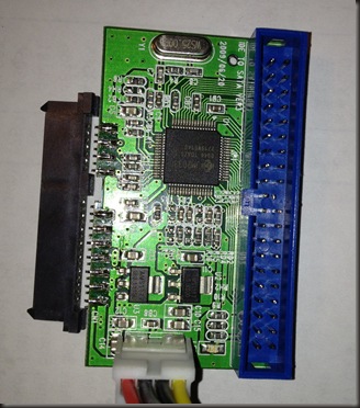
broken connector

When I installed this set up, the adaptor worked great, although its mechanical construction was flimsy. The SATA connector on this device is a through-hole connector repurposed as an edge connector.  In the photo above you’ll see that the connector is no longer attached to the motherboard.

As verified each component of the computer, one by one. The only failure, it turned out, was the SATA to IDE adaptor. That was good news, however, soldering those 20-plus contacts would be impossible, and my dear wife was anxious to use her computer. What to do?

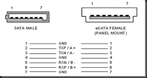
At some point I noticed that the big section of the connector was for SATA power. Power is easy to come by, so this part of the connector seemed unnecessary. The smaller section of the connector is SATA data. I Googled SATA data and took a quick primer on all things SATA. SATA data is a pretty clean high speed bus. It is composed of 7 signal connections. The seven wires are: two differential  pairs (in and out) and three ground connections. However, soldering the original connector back into place was just too difficult.
image

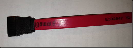
I surmised that the transceiver on the adaptor could carry the signal past the original connection point by a few more inches without problem. I would solder cable end in place of the original connector. I ran to radio Shack and bought a SATA data cable. Once I was back home, I cut the cable in half and prepared the wires.
image

It’s a flat cable so it was a breeze to verify the proper pin out. The cable jacket was elegant. Each twisted pair was in its own section wrapped in foil with two ground wires.
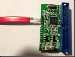
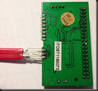
image  image

I connected everything 1 to 1, save for pin 4, where I connected two ground wires, one each from the two twisted pair bundles. With a little bit of electrical tape to protect from shorting, I was ready to roll.
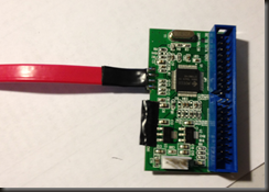
image

I plugged the IDE cable into the adaptor, as well as a power cable. On the drive, I plugged in a SATA power cable  from the power supply harness and the SATA data cable end that I had soldered onto the adaptor board. I powered up the computer. It booted up and has run fine ever since.

I now know a lot more about SATA and once again, I performed some intense hardware surgery and the patient survived!

Blank Shield Schematic for Arduino Uno

•December 25, 2011 • Leave a Comment


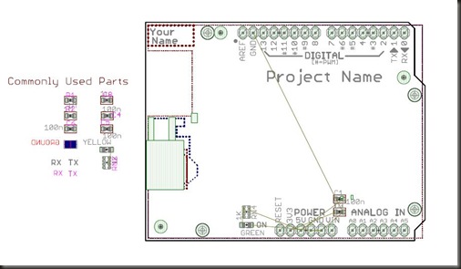
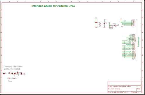
For a recent project, I created a shield template for the Arduino Uno. MOST of the bugs are out, as I did use it once and then corrected the few shortcomings that I encountered. These linked files should give you a decent head start over creating your own shield in Eagle CAD or adapting an existing design for your needs.

assy dwg

What I did: Starting with the UNO reference schematic, I removed the parts that I did not need and left the parts necessary to interface to the Uno.

image

I made a shield template that puts the user at this starting point:

    • All schematic parts are on the 0.1 default grid. (Until you try to
Technorati Tags: ,,
  • work with with parts off of the grid, you’ll not appreciate how frustrating this can be.
  • I put all important top side text on to layer 21 so that my preprocessor put the text onto the Gerber file silk layer.
  • I put all of the Arduino interface connectors on the far right side of the schematic because I like my circuit to flow left to right.
  • I framed the schematic.
  • On a hunch, I left a few filter caps and LEDs on the board.
  • Also I have a section of called Commonly Used Parts. <Common Sense alert> If you don’t use ‘em, delete ‘em.

Get the schematic and layout in a zip file here:
http://www.mediafire.com/?0kt85e6i0tc7ol0

Hard Disk Repair – Not for the Faint of Heart

•October 9, 2011 • Leave a Comment

Recently I updated our two computers with new cases. Not a big deal, as far as upgrades go. It started when my power supply fried. It was cheaper to buy two brand-new cases with power supplies from Newegg than it was buy one power supply from Best Buy.

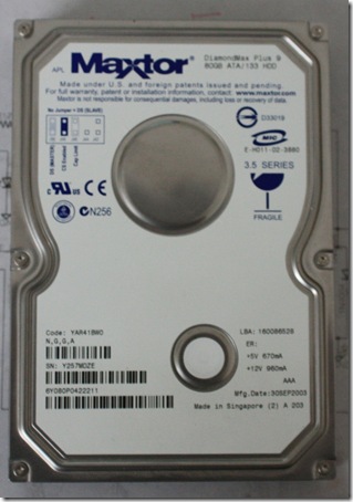
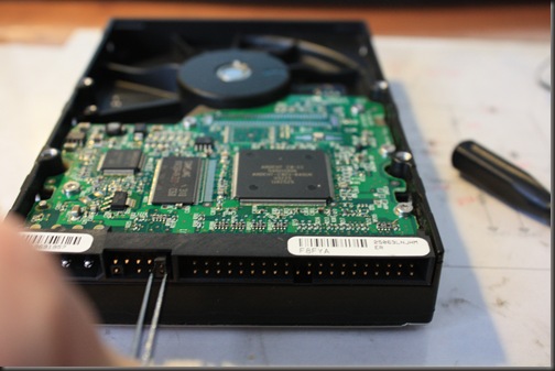
hdd

When swapping the components in my wife’s computer, I noticed that one of the HDD was hot to the touch. Now anyone familiar with the inside of a computer case knows that warm is OK and hot is cause for concern. Like most people in a hurry, I went about my business and ignored this leading indicator of a problem. Two days later I got a call “ITunes can’t find my music files.” The problem, and its diagnosis, flashed before my eyes instantly. Later that day I confirmed my suspicion. The drive was now stone cold dead. Luckily this was the secondary drive (D:) and all it held was mp3 files.

the patient

I started to Google “drive recovery”. Somehow I got on to drive repair web sites. Forty bucks would get me a used, tested replacement circuit board for my Maxtor 80GB hard drive. The majority of these sites were from Asian companies with broken English explanations of the repair process. It seemed daunting, because a few steps alluded to implicit contingencies on how to repair my HDD.

Most troubling was this instruction:

In most cases, you should exchange the BIOS chip before you swap hard drive PCB;

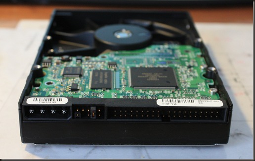
Holey molé! How do I determine if this applies to me? And worse still, I didn’t have the friendly little eight-pin SMT BIOS IC like many drives have. Do I need to swap out the 168 pin QFP? Not with my equipment.

Soon, through EBay, I found the web page for PCB Solution. I use their web site to find my matching PCBA and sent them an email. Although it was now midnight I got an immediate reply from Kevin:

This board is direct swap. Some board required more work, but not this one. If you prefer, you can tell me the current symptoms of your hard drive, and I can give you an estimate on your odds of success. There are no refunds with this purchase. I hope this helped and please let me know if you have any other questions. 

So in my return email, I explained my plight. Kevin’s response contained the helpful response that I needed:

If the drive doesn't spin up, and wasn't dropped, I think the chances of
success are quite good.

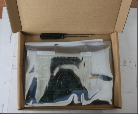
Bingo! I could proceed with confidence. I ordered the PCBA through eBay and waited. When it arrived, I opened the package and the contents impressed me.

hdd box

I expected to see the PCBA wrapped in a metalized poly bag. It also came with clearly written instructions and a Torx screwdriver. Great!


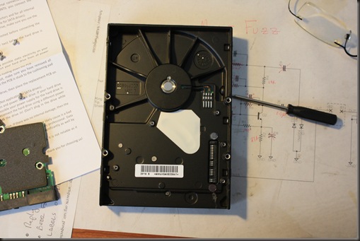
1 – Remove the PCBA

IMG_4509

In the picture, notice: (1) Torx drive, (2) PCBA covered with rubber membrane, HDD, (4) loose Torx screws, (5) replacement instructions and (6) spring pin contacts to interface the PCBA to the HDD chassis. At this point I was still wondering if I had squandered $40.


2 –Installation

Simply put the membrane on the replacement PCBA and screw it in.  The spring pin contacts on the HDD chassis help to make replacement a breeze.

IMG_4510

3 – Configure

Simply put the jumper on the new board so it is configured like the old board. If you lose track, simply follow the graphic on the front of the drive.

4 – Test

I installed the drive in my computer, and booted up. Success!

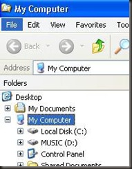
test

Drive D: is fully recovered and operational.

Effect Number Two: Muff Fuzz Complete

•July 5, 2011 • Leave a Comment

RAW Squid

We’ll, the Muff Fuzz is complete. It looks good too. While it obviously is an amateur effort, it came out a lot better than I expected. It is named after a friend who helped me quite a few times through this project. In retrospect, RAW Squid is a bad-ass name for the fuzz box.

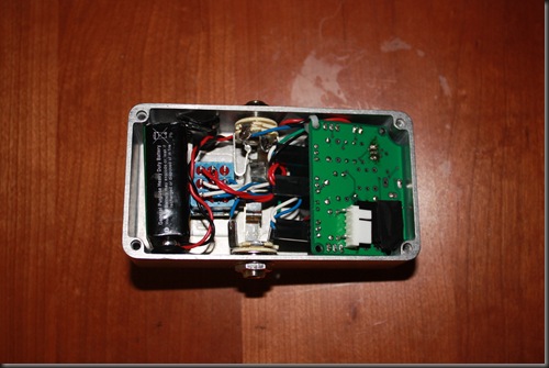
In my last post, I commented that I was having trouble getting everything to fit. In the end, I was able to fit everything inside this little old Hammond 1590B enclosure, but it is tight inside. I was able to keep the PCBA connectors, so everything is readily interchangeable. If I continue to build guitar effect pedals I’ll design for a slightly bigger enclosure.

IMG_4481

The original Muff Fuzz had a volume pot, but no tone control. I elected to go without a volume pot. That may be a mistake, as the output from this pedal is louder than straight through bypass. If required, we can add one later. I built this effect with true bypass. I don’t know how the original Muff Fuzz bypass was set up.

On the circuit board, you’ll notice the white connector. The connector hosts a plug in module for the clipping diodes. You can see the clipping diodes in the schematic diagram below. I installed the clipping diodes in a plug in module so that the pedal is easy to experiment with.

The most basic mode (1) is no diodes. Without clipping diodes the circuit is essentially a Fuzz Face with alternate component values. Configured this way, the sound is similar to, but has more buzz than a Fuzz Face. Adding the back-to-back clipping diodes, (2) the circuit is as shown above. Lastly (3) I made a  a three diode version where one of the legs has with two diodes in series. A lot of folks call that the tube screamer mod because the diode clipping is asymmetrical.

We could make even more versions, if we were to toss germanium diodes and filter capacitors into the mix.  Also, I suspect that tone control could be added in place of the 2.7k ohm resistor.

I’m eager to have this effect pedal evaluated by an objective and seasoned guitar player.


Effect Number Two: Designing in Three Dimensions

•June 13, 2011 • Leave a Comment

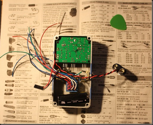
For my 2nd effect, I planned to build a Muff Fuzz. It looks like I’ll have to take a step back on this one. This is destined for a friend, how has served as my music industry consultant. My idea was to have the circuit connectorized so that we could easily swap the circuit. Also, I wanted to put it into a sleeker case than my first Fuzz effect. I now know that the beautiful Hammond 1590B enclosure can accommodate the circuitry, but not the connectorization scheme.

small box

It looks like I’ll have to hardwire the components. Luckily, this does not preclude all experimentation. The Muff Fuzz is essentially a Fuzz Face front end, with clipping diodes on the output, like an MXR Distortion+.  There are many ways to select and configure the output diodes. Soon, we may know which are the most interesting combinations.

Parting Thoughts on the DOD FX55

•June 10, 2011 • Leave a Comment

After I fixed the effect, I put it back together, finger-tight. That is, installed all of the hardware and screwed the hex nuts on finger tight. So everything was assembled, but loosely.

I inserted the FX55 in the signal path, between my guitar and amp. Instant success. But, wait I couldn’t turn it off! Actually every time I stepped on the switch, I heard a click coming out of the amp, but the  effect remained ON. Well this effect uses active switching, rather than true bypass. The schematic indicated that the case played no active role in the circuitry. The problem was one of these two choices (1) circuit noise or (2) I broke something. After tightening all of the hex nuts and screwing the case on securely everything worked fine. Note to self: this item is noise sensitive.

Get your own 5 in 1 effects PCB

•June 1, 2011 • Leave a Comment

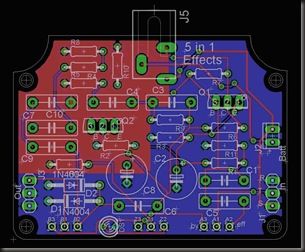
If my guitar effects projects interests you and you’d like to build your own guitar effect, then you can get your own circuit board at Batch PCB. You can choose one of the circuits listed in the Burnout Sound schematics page, or a few others as well. For example I am presently building a Muff Fuzz circuit on the 5 in 1 PCB.

5 in 1 PCB

The PCB has both a ground and a VCC plane . There are provisions for both battery and line power and a circuit board is so much cleaner and rugged as compared to perf board construction methods. It available from Batch PCB. With shipping and handling, it’s more expensive that I’d like, but I do not set the prices.